


#1 Industrial motherboard burned capacitpr on negative (-5V) power supply rail
przez matic • 16 lutego 2020, 14:11
Hello!
I'm working on motherboard from old CNC machine.
Markings on the motherboard are on the following picture. The schematic is most likely not available.


I found a burned tantalum capacitor, but the PCB board is also burned in the vicinity of this capacitor:

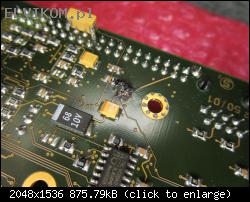
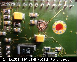
And the pictures of the same area of the board after cleaning:

The input for negative (-5V) power rail is on the header above the burned area. It comes from -5V LDO regulator (MC7905CT), which is located on another power supply board.
I think that the -5V power rail is interrupted somewhere on the burned area. The resistance to ground on this power rail is out of range of my meter (more than 40MΩ). I also tried to inject -5V from the laboratory power supply, but there is no power consumption on this power rail.
Any idea, on which component the -5V power rail is connected?
I'm working on motherboard from old CNC machine.
Markings on the motherboard are on the following picture. The schematic is most likely not available.


I found a burned tantalum capacitor, but the PCB board is also burned in the vicinity of this capacitor:

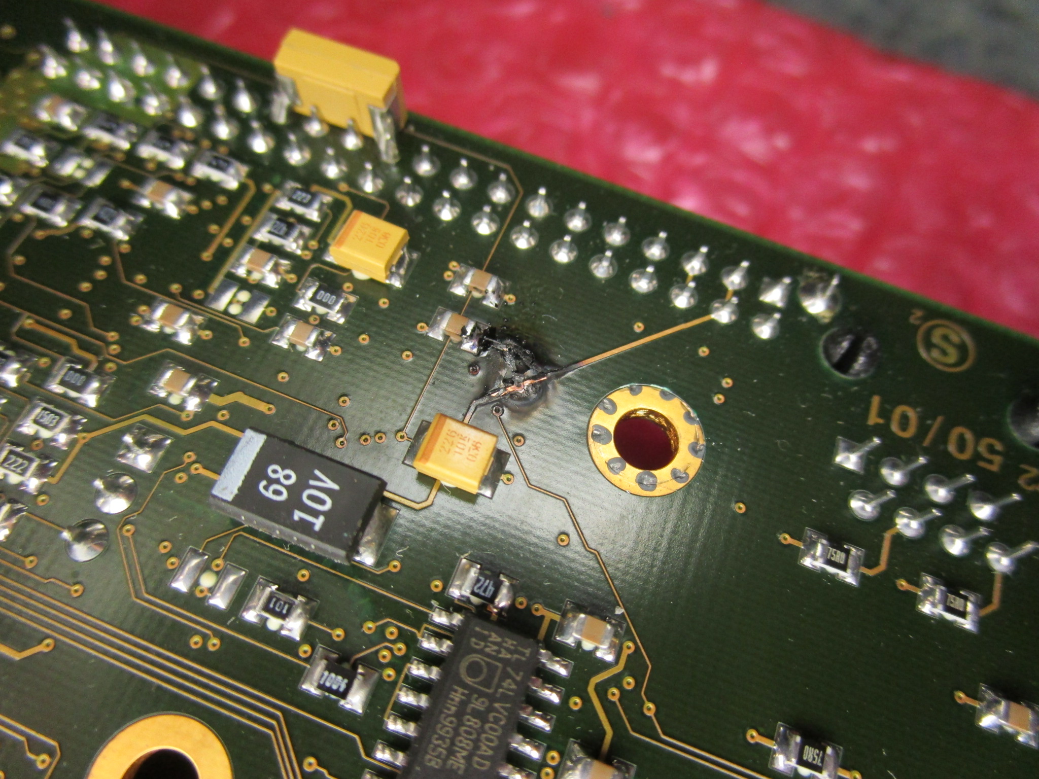
And the pictures of the same area of the board after cleaning:


The input for negative (-5V) power rail is on the header above the burned area. It comes from -5V LDO regulator (MC7905CT), which is located on another power supply board.
I think that the -5V power rail is interrupted somewhere on the burned area. The resistance to ground on this power rail is out of range of my meter (more than 40MΩ). I also tried to inject -5V from the laboratory power supply, but there is no power consumption on this power rail.
Any idea, on which component the -5V power rail is connected?


