

#1 Toshiba Satellite L555-10W Issue with "+1.05VSP" power supply line
przez matic • 14 marca 2017, 01:04
Motherboard: Compal LA-4982P, Rev.: 1.0
Hello!
Listed laptop normally turns ON, but the screen stays black (no backlight, no picture).
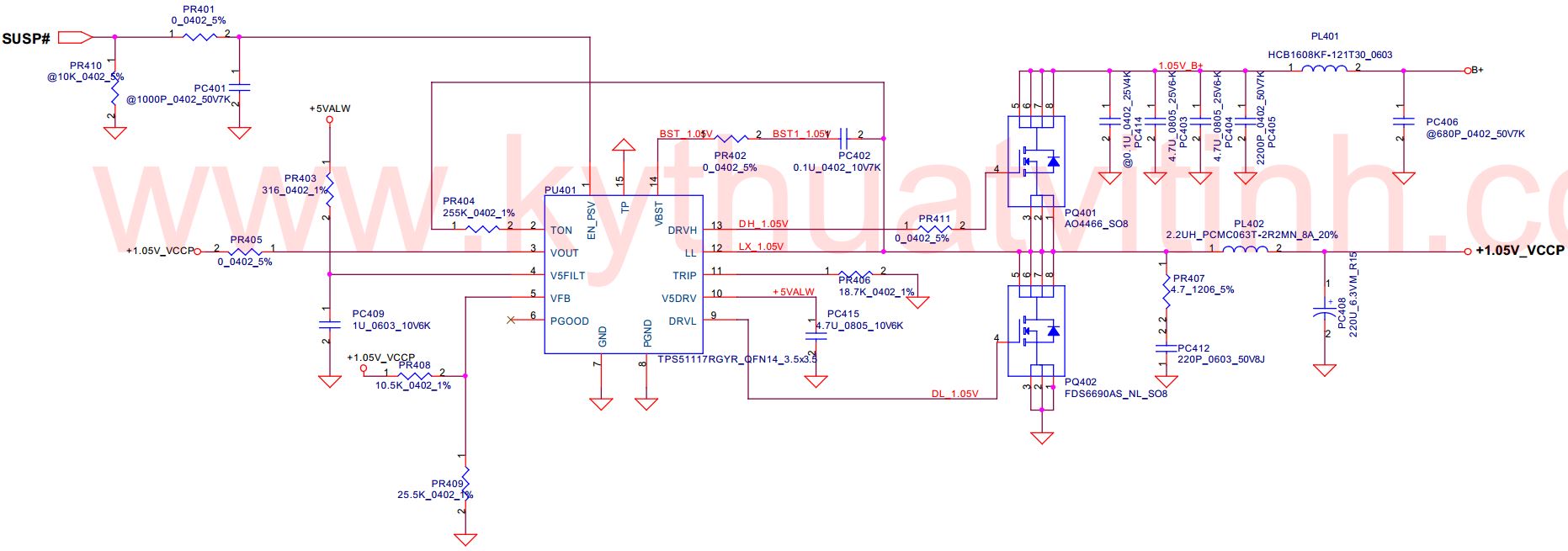
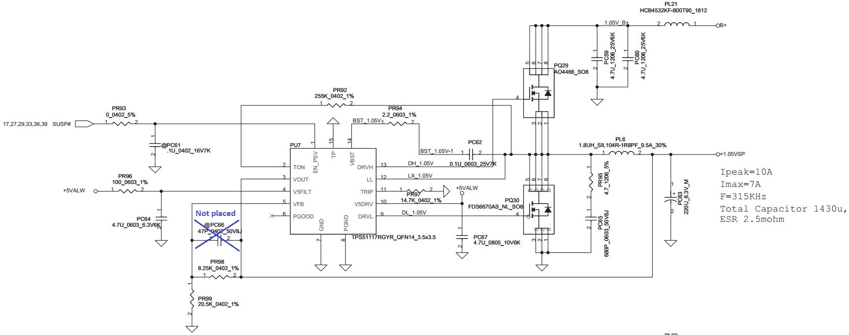
I found out that the problem is on the "+1.05VSP" power supply line. Voltage on this line is only 0,82V instead 1,05V. The strangest thing is that the voltage on "+1.05VSP" line becomes ok, if I heat up the switching controller chip "PU7" (TPS51117), and everything works ok.
The chip must be heated on about 40°C or more to function properly. It is necessary to heat up only the chip (not surrounding components). I tried to precisely heat it up with the tip of the soldering iron.
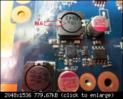
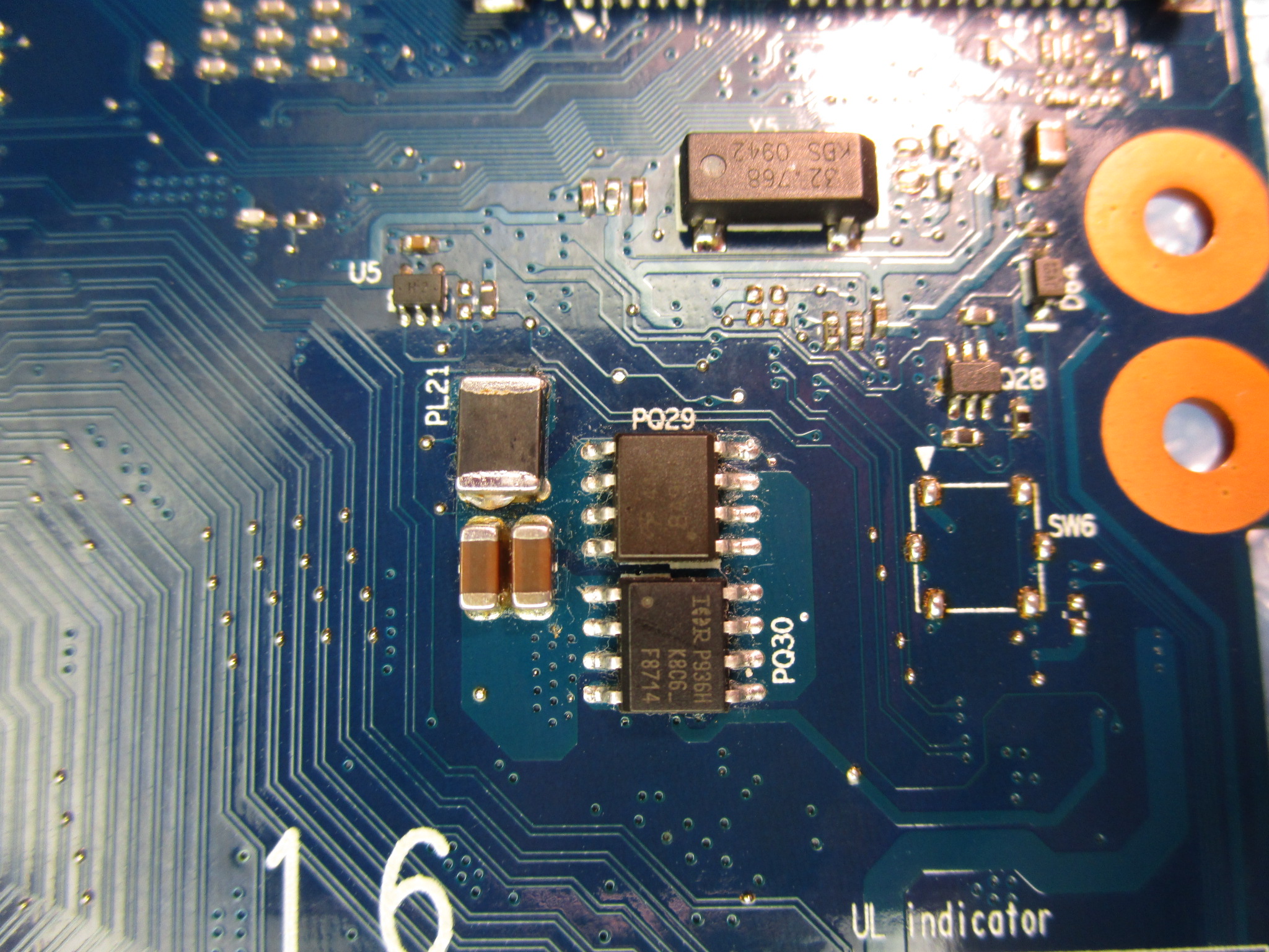
Pictures of the top side of the board, bottom side of the board and part of the schematic:

Datasheet of the chip "PU7" (TPS51117) is in the attachment.
Voltages, when the chip "PU7" is not working properly:
Output voltage (on capacitor "PC63"): 0.82V
Enable (pin 1 of "PU7"): 3.23V
5V logic supply (pin 4 of "PU7"): 5.06V
Feedback (pin 5 of "PU7"): 0.55V
Power supply (on booth ends of coil "PL21"): 19.15V
What I've tried up to now:
-Chip "PU7" replaced three times with different chips. One pulled from scraped board, the other two was brand new ones. -> The same issue
-Replaced surrounding components: resistors PR92, PR93, PR96, PR97, PR98, PR99, capacitors PC61, PC62, PC64, and PC67 -> The same issue
-Removed jumpers "PJ6" and "PJ9" -> In this case the output voltage 1.05V is ok regardless of whether the chip "PU7" is warm or not.
I'm out out of ideas now...
Any advice and suggestions would be greatly appreciated.
Hello!
Listed laptop normally turns ON, but the screen stays black (no backlight, no picture).
I found out that the problem is on the "+1.05VSP" power supply line. Voltage on this line is only 0,82V instead 1,05V. The strangest thing is that the voltage on "+1.05VSP" line becomes ok, if I heat up the switching controller chip "PU7" (TPS51117), and everything works ok.
The chip must be heated on about 40°C or more to function properly. It is necessary to heat up only the chip (not surrounding components). I tried to precisely heat it up with the tip of the soldering iron.
Pictures of the top side of the board, bottom side of the board and part of the schematic:

Datasheet of the chip "PU7" (TPS51117) is in the attachment.
Voltages, when the chip "PU7" is not working properly:
Output voltage (on capacitor "PC63"): 0.82V
Enable (pin 1 of "PU7"): 3.23V
5V logic supply (pin 4 of "PU7"): 5.06V
Feedback (pin 5 of "PU7"): 0.55V
Power supply (on booth ends of coil "PL21"): 19.15V
What I've tried up to now:
-Chip "PU7" replaced three times with different chips. One pulled from scraped board, the other two was brand new ones. -> The same issue
-Replaced surrounding components: resistors PR92, PR93, PR96, PR97, PR98, PR99, capacitors PC61, PC62, PC64, and PC67 -> The same issue
-Removed jumpers "PJ6" and "PJ9" -> In this case the output voltage 1.05V is ok regardless of whether the chip "PU7" is warm or not.
I'm out out of ideas now...
Any advice and suggestions would be greatly appreciated.