• How can i test a smd component used in a tv source Samsung PL51F4000 XZ0

Forum rules:Click here to view the forum rules

  1. Topic title should contain the brief description of problem.
  2. Topic message should contain the extended description of problem and, the question.
  3. It is not allowed to post the attachments with complete documentations or BIOS files nor linking to any 3rd party websites hosting such files. It is only allowed to post the small portion of the documentation (up to one page per post).
  4. You can only describe one problem per topic. For each another problem you should open a new topic.
  5. It is strictly forbidden to ask for any kind of documentation or BIOS file. For such requests please use the DOCUMENTATION & BIOS/EFI REQUEST subforum.
This topic is marked as ARCHIVAL. Please only reply if your message contains the solution (Terms and Conditions p. 12.1).

#1 How can i test a smd component used in a tv source Samsung PL51F4000 XZ0


by eletmoraes 21 July 2017, 21:00
I have a Samsung Plasma TV PL51F4000 XZ0 lcd that I suspect the integrated LTV-155E photo-coupler may be damaged. I'd like to help you figure out how I can test this component to see if it's good or not.

Image

Re: How can i test a smd component used in a tv source Samsung PL51F4000 XZ0


by Google Adsense [BOT] 21 July 2017, 21:00

#2 Re: How can i test a smd component used in a tv source Samsung PL51F4000 XZ0


by Vogelek23 22 July 2017, 00:07
eletmoraes wrote:LTV-155E
There is a TLP155E from Toshiba on your photo.

eletmoraes wrote:I'd like to help you figure out how I can test this component to see if it's good or not.
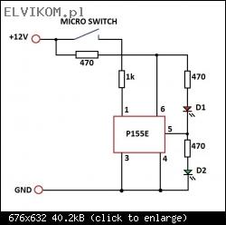
Please build a simple test environment as shown below:
Post edited - all the content below has been changed!

Image

For initial state (switch not pressed) there is normally a LOW (0V) level on output pin 5 - D1 (red) LED is switched ON and D2 (green) LED is switched OFF. When you press and hold the switch, output pin 5 changes to HIGH (12V) level - D1 (red) LED should be switched OFF and D2 (green) LED should be switched ON. When you release the switch, all the circuit should go back to the initial state (D1 on, D2 off).

Optocoupler is faulty if both D1 and D2 are switched ON or OFF at the same time.

#3 Re: How can i test a smd component used in a tv source Samsung PL51F4000 XZ0


by matic 22 July 2017, 14:32
You can also measure resistance between pins 4 and 5, and between pins 5 and 6. If any of this resistance is low the chip is bad. If both resistances is high (in kΩ or MΩ range) you should test the chip to the schematic like @Vogelek23 suggested.

Re: How can i test a smd component used in a tv source Samsung PL51F4000 XZ0


by Google Adsense [BOT] 22 July 2017, 14:32
This topic is marked as ARCHIVAL. Please only reply if your message contains the solution (Terms and Conditions p. 12.1).

Who is online

Users browsing this forum: No registered users and 0 guests

_______________________________
All rights reserved. Unauthorised copying of this website's content or any of its part is strictly forbidden.
Any trademarks, brand names, products or services published on this website belong to their legal owners, are copyrighted and used for information purposes only.