Forum rules: Click here to view the forum rules
- Topic title should contain: the device's manufacturer, full model and the brief description of problem.
- Topic message should contain: the PCB marking code (required in case of hardware repairs), an extended description of problem, things you have checked/replaced/measured, your conclusions and the question. If you are not able to find the PCB marking code, please read THIS TOPIC. If you still cannot locate the PCB markings, please upload a clean, both-side photos of the mainboard - it is required to remove any films, modules or brackets possibly covering these markings.
- Before posting a new topic please read all topics in TRAININGS subforum and make a preliminary diagnostic based on the content of those trainings.
- Uploading of any complete schematics, BIOS / firmware files or any other kind of documentation, or linking to 3rd party websites with such files, is STRICTLY PROHIBITED. You can only upload the small portion of documentation or, link to BIOS file on UNVERIFIED BIOS FILES subforum, which simplifies the diagnostics/repair. You are not allowed to upload more then one complete page of instruction/schematic per single topic. The file you upload must not contain any watermarks, "confidential" markings, links or email addresses and cannot be password-protected.
- It is only permitted to describe one faulty device per single topic - you should always open a new topic for each subsequent device.
- Requesting of the full schematics, BoardView files, BIOS files or any other kind of documentation is NOT ALLOWED in this subforum. If you need to ask for any of these, you should open a new topic in DOCUMENTATION/BIOS REQUEST subforum.
This topic is marked as ARCHIVAL. Please only reply if your message contains the solution (Terms and Conditions p. 12.1).
Re: PS3 4004 MSX-001 identyfikacja elementu
by Google Adsense [BOT] • 19 August 2017, 18:01
Hello!
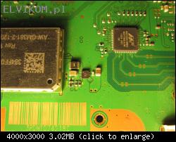
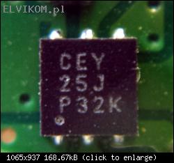
It is switching controller chip for 1.8V WiFi module power supply. This chip goes bad very often on Super slims.
Datasheet is not available, because this chip is custom made for Sony.
The information that I've discovered about this chip:
-Step down switching DC/DC converter with enable input
-Input voltage: 5.5V
-Adjustable output voltage
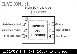
-6-pin SON package with thermal pad
-Pinout:

I think it is only option to use any similar chip in the same package and the same pinout. In this case it is necessary to change the inductor value and values of tiny caps and resistors near the chip.
I did it few times and it works without problems.
I used chip TPS62290 (datasheet in the attachment).
The values of inductor and other tiny components are dependent of the chip type. It is described in datasheet of the chip.
Components that should be replaced (values are for the chip TPS62290):

1) Replace with inductor 2.2uH, package: 0806
2) Replace with resistor 360kΩ, 1%, package: 0402
3) Replace with bridge or resistor 0R, package: 0402
4) Replace with capacitor 22pF, package: 0402
5) Replace with resistor 180kΩ, 1%, package: 0402
All components are availabe here:
Chip TPS62290
Inductor 2.2uH
Resistor 0R
Resistor 180kΩ
Resistor 360kΩ
Capacitor 22pF
After replacing all of the described components first power it on without WiFi module and measure the output voltage. If it is ok (1.8V) solder new WIFI module (or replace Marwell QFN chip on the WiFi module, which goes bad) and it should work.
It is switching controller chip for 1.8V WiFi module power supply. This chip goes bad very often on Super slims.
Datasheet is not available, because this chip is custom made for Sony.
The information that I've discovered about this chip:
-Step down switching DC/DC converter with enable input
-Input voltage: 5.5V
-Adjustable output voltage
-6-pin SON package with thermal pad
-Pinout:

I think it is only option to use any similar chip in the same package and the same pinout. In this case it is necessary to change the inductor value and values of tiny caps and resistors near the chip.
I did it few times and it works without problems.
I used chip TPS62290 (datasheet in the attachment).
The values of inductor and other tiny components are dependent of the chip type. It is described in datasheet of the chip.
Components that should be replaced (values are for the chip TPS62290):

1) Replace with inductor 2.2uH, package: 0806
2) Replace with resistor 360kΩ, 1%, package: 0402
3) Replace with bridge or resistor 0R, package: 0402
4) Replace with capacitor 22pF, package: 0402
5) Replace with resistor 180kΩ, 1%, package: 0402
All components are availabe here:
Chip TPS62290
Inductor 2.2uH
Resistor 0R
Resistor 180kΩ
Resistor 360kΩ
Capacitor 22pF
After replacing all of the described components first power it on without WiFi module and measure the output voltage. If it is ok (1.8V) solder new WIFI module (or replace Marwell QFN chip on the WiFi module, which goes bad) and it should work.
Re: PS3 4004 MSX-001 identyfikacja elementu
by Google Adsense [BOT] • 19 August 2017, 19:05
This topic is marked as ARCHIVAL. Please only reply if your message contains the solution (Terms and Conditions p. 12.1).
Who is online
Users browsing this forum: No registered users and 0 guests
_______________________________All rights reserved. Unauthorised copying of this website's content or any of its part is strictly forbidden.
Any trademarks, brand names, products or services published on this website belong to their legal owners, are copyrighted and used for information purposes only.


