• [SCHEMATIC REQUEST] Schemat podłączenia MEC1633L Lenovo T440

This topic is marked as ARCHIVAL. Please only reply if your message contains the solution (Terms and Conditions p. 12.1).

#1 [SCHEMATIC REQUEST] Schemat podłączenia MEC1633L Lenovo T440


by McMemorek 23 November 2020, 09:10
Witam serdecznie.

Poszukuje schemat podłączenia się pod pady na MB laptopa Lenovo ThinkPad
T440 (model płyty NM-A102 Rev. 1.0) w celu przeprogramowania układu SMSC (układ o nazwie MEC1633L) .
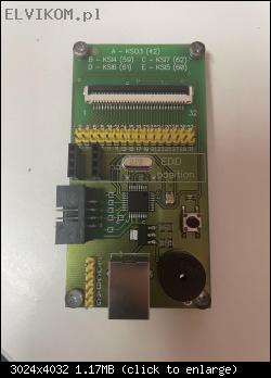
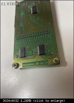
Kupiłem programator Verrtyanov w wersji 2.0, mam dostęp do w pełni
sprawnego układu, z którego wyciągnę wsad, ale nie mam pojęcia jakimi
kabelkami wpiąć się do padów o oznaczeniu J20 na schemacie płyty głównej.
Coś tam niby poszperałem i póki co wyszło mi takie coś:


1. wire is not user Reset for ATMEGA 88 -- > MEC_DBG_RST
2. wire 60 output EDI_CLK / KSI 5 -- > JTAG_CLK
3. wire 62 output EDI_DO / KSI 7 --> JTAG_TDO
4. wire is not supported user output 3v3 / 100mA --> xxxxxxx
5. wire 61 output EDI_DIN / KSI 6 --> JTAG_TDI
6. wire GND --> GND
7. wire 59 output EDI_CS / KSI4 --> JTAG_TMS ???????

Mam dylemat co do pkt 7 czy na pewno ma byc podpiety do JTAG TMS ? Reszta
podłączeń jest ok ?

Dodam, że o ile z programowaniem układów BIOS nie mam żadnych problemów - o
tyle programowanie KBC będę robił pierwszy raz w swoim życiu ;) no ale
kiedyś musi być ten ,, pierwszy raz,,

Z góry dziękuje za pomoc i poświęcony czas.

Re: [SCHEMATIC REQUEST] Schemat podłączenia MEC1633L Lenovo T440


by Google Adsense [BOT] 23 November 2020, 09:10

#2 [SCHEMATIC REQUEST] Re: Schemat podłączenia MEC1633L Lenovo T440


by matic 23 November 2020, 12:13
Hello!

The MEC KBC chips can be programmed via "JTAG" interface.

You need to connect the following signals:
  • JTAG_TDI
  • JTAG_TDO
  • JTAG_CLK (JTAG_TCK)
  • JTAG_TMS
  • JTAG_RST (JTAG_RESET)
In addition to this signals you should also connect the ground (GND) between the motherboard and programmer. You can connect it via USB cable.

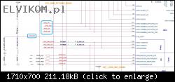
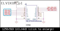
On your particular board this signals are accessible on "Debug" connector J20. This connector is actually not soldered to the board, so you have to solder the wires on pins of this connector (schematic parts below).

Image
Image

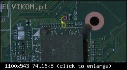
You can see that all of the signals (except the reset JTAG_RST (JTAG_RESET)) are accessible to the connector J20. This reset signal is usually not needed for programming, so you can try to program this chip without connecting this signal. It is only need to pull this reset signal to high level (currently it is pulled low to the board), so you need to swap the resistor R8797 to the place of R8796 (move the following resistor from red to the yellow place):
Image

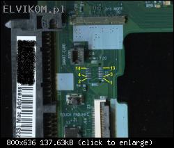
"Debug" connector J20 on the board with pin count:
Image

After connecting all of the wires you should connect the power supply to the board, because the KBC chip should be powered during the programming.

#3 [SCHEMATIC REQUEST] Re: Schemat podłączenia MEC1633L Lenovo T440


by McMemorek 23 November 2020, 13:20
matic wrote:Hello!

The MEC KBC chips can be programmed via "JTAG" interface.

You need to connect the following signals:
  • JTAG_TDI
  • JTAG_TDO
  • JTAG_CLK (JTAG_TCK)
  • JTAG_TMS
  • JTAG_RST (JTAG_RESET)
In addition to this signals you should also connect the ground (GND) between the motherboard and programmer. You can connect it via USB cable.

On your particular board this signals are accessible on "Debug" connector J20. This connector is actually not soldered to the board, so you have to solder the wires on pins of this connector (schematic parts below).

[ Obrazek ]
[ Obrazek ]

You can see that all of the signals (except the reset JTAG_RST (JTAG_RESET)) are accessible to the connector J20. This reset signal is usually not needed for programming, so you can try to program this chip without connecting this signal. It is only need to pull this reset signal to high level (currently it is pulled low to the board), so you need to swap the resistor R8797 to the place of R8796 (move the following resistor from red to the yellow place):
[ Obrazek ]

"Debug" connector J20 on the board with pin count:
[ Obrazek ]

After connecting all of the wires you should connect the power supply to the board, because the KBC chip should be powered during the programming.


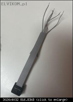
Thanks for the answer, but I meant something else. My point is to match the signals from the programmer to the signals on the motherboard. Which cable should be soldered to which pad. Sorry for the mistakes with the language, I use the translator

#4 [SCHEMATIC REQUEST] Re: Schemat podłączenia MEC1633L Lenovo T440


by matic 23 November 2020, 13:38
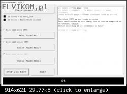
Please, post a picture of your programmer.

#5 [SCHEMATIC REQUEST] Re: Schemat podłączenia MEC1633L Lenovo T440


by McMemorek 23 November 2020, 13:42
matic wrote:Please, post a picture of your programmer.


Image

Image

Image

Image

#6 [SCHEMATIC REQUEST] Re: Schemat podłączenia MEC1633L Lenovo T440


by matic 23 November 2020, 15:02
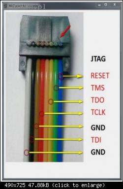
The cable pinout is probably the same as at other versions of Vertyanov programmer:
Image

#7 [SCHEMATIC REQUEST] Re: Schemat podłączenia MEC1633L Lenovo T440


by McMemorek 25 November 2020, 14:35
matic wrote:The cable pinout is probably the same as at other versions of Vertyanov programmer:
[ Obrazek ]


Thanks for the answer, it turned out that the laptop with a working batch has a bios password, am I able to remove it with this programmer using this method? This is the only computer with an efficient KBC and I cannot upload the password to the second computer, the boss will not allow it :(

[SCHEMATIC REQUEST] Re: Schemat podłączenia MEC1633L Lenovo T440


by Google Adsense [BOT] 25 November 2020, 14:35
This topic is marked as ARCHIVAL. Please only reply if your message contains the solution (Terms and Conditions p. 12.1).

Who is online

Users browsing this forum: No registered users and 1 guest

_______________________________
All rights reserved. Unauthorised copying of this website's content or any of its part is strictly forbidden.
Any trademarks, brand names, products or services published on this website belong to their legal owners, are copyrighted and used for information purposes only.