• Lenovo ThinPad T470 NM-A931 rev 2.0 Schemat podłączenia JTAG MEC1653 SVOD3

Forum rules:Click here to view the forum rules

  1. Topic title should contain the brief description of problem.
  2. Topic message should contain the extended description of problem and, the question.
  3. It is not allowed to post the attachments with complete documentations or BIOS files nor linking to any 3rd party websites hosting such files. It is only allowed to post the small portion of the documentation (up to one page per post).
  4. You can only describe one problem per topic. For each another problem you should open a new topic.
  5. It is strictly forbidden to ask for any kind of documentation or BIOS file. For such requests please use the DOCUMENTATION & BIOS/EFI REQUEST subforum.
This topic is marked as ARCHIVAL. Please only reply if your message contains the solution (Terms and Conditions p. 12.1).

#1 Lenovo ThinPad T470 NM-A931 rev 2.0 Schemat podłączenia JTAG MEC1653 SVOD3


by AndyWilly 11 January 2021, 17:37
Laptop Lenovo ThinPad T470
Płyta: NM-A931 rev 2.0

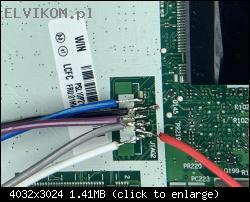
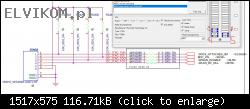
Szukam schematu podłączenia MEC1653 po interfejsie JTAG w celu jego zaprogramowania . Po podłączeniu pokazanym na zdjęciu programator SVOD3 nie wykrywa układu. Podłączam zasilanie do płyty głównej poprzez złącze zasilania nadal nie wykrywa, podawałem 3V 0,1A na pin6(JTAG) również nie wykrywa.

Schemat połączenia jaki użyłem:
(PIN)JTAG (PIN)SVOD3
1.TMS 1.TMS
2.TDI 5.TDI
3.TDO 2.TDO
4.TCK 6.CLK
5. GND 4.GDN
6.- .-
Image

Image

Re: Lenovo ThinPad T470 NM-A931 rev 2.0 Schemat podłączenia JTAG MEC1653 SVOD3


by Google Adsense [BOT] 11 January 2021, 17:37

#2 Re: Lenovo ThinPad T470 NM-A931 rev 2.0 Schemat podłączenia JTAG MEC1653 SVOD3


by matic 11 January 2021, 18:29
Hello!

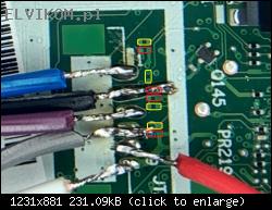
First of all it is need to solder the missing components to "enable" the JTAG2 connector, because they are factory omitted to reduce the costs.
You have to solder 8 missing resistors and switch one resistor to another location.
The solder pads for missing resistors are covered with a solder mask, so you need to remove it from the pads that you will be able to solder the missing resistors. To do that it is best to use a "Fiberglass pencil" (following picture).
Image

Solder the missing components to the highlighted locations (picture below).
Red= Resistor 10kΩ/5%, package 0201
Yellow= Resistor 0Ω (Jumper), package 0201
Image

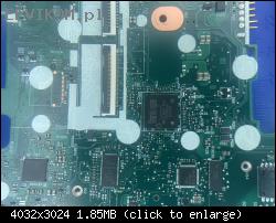
Plese, post a clear picture of the KBC chip area with a nearby surroundings that I can highlight the resistor, that needs to be switched to another location.

#3 Re: Lenovo ThinPad T470 NM-A931 rev 2.0 Schemat podłączenia JTAG MEC1653 SVOD3


by AndyWilly 11 January 2021, 19:07
Image

#4 Re: Lenovo ThinPad T470 NM-A931 rev 2.0 Schemat podłączenia JTAG MEC1653 SVOD3


by matic 11 January 2021, 20:15
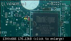
Switch the highlighted resistor from red to yellow position (picture below):
Image

Re: Lenovo ThinPad T470 NM-A931 rev 2.0 Schemat podłączenia JTAG MEC1653 SVOD3


by Google Adsense [BOT] 11 January 2021, 20:15
This topic is marked as ARCHIVAL. Please only reply if your message contains the solution (Terms and Conditions p. 12.1).

Who is online

Users browsing this forum: No registered users and 2 guests

_______________________________
All rights reserved. Unauthorised copying of this website's content or any of its part is strictly forbidden.
Any trademarks, brand names, products or services published on this website belong to their legal owners, are copyrighted and used for information purposes only.