• Lenovo Y50-70 ZIVY2 LA-B111P rev: 1A Y50-70 brak sygnału VGATE

Regole del forum:Clicca per leggere le regole del forum

  1. Il titolo dell'argomento deve contenere: marca e modello completo del dispositivo e la breve descrizione del problema.
  2. Il messaggio di argomento dovrebbe contenere: un identificatore PCB (in caso di riparazioni hardware), descrizione estesa del problema, cosa è stato controllato/sostituito/misurato, eventuali conclusioni e la domanda. Se non riesci a individuare un identificatore PCB, leggi QUESTO ARGOMENTO. Se non riesci ancora a individuare un identificatore PCB, invia foto chiare di entrambi i lati della scheda madre; è necessario rimuovere qualsiasi pellicola o altri elementi che potrebbero coprire questo identificatore.
  3. Prima di pubblicare un nuovo argomento, leggere tutti gli argomenti nel subforum CORSI e fare una diagnosi preliminare basata sul contenuto di questi corsi.
  4. È VIETATO caricare diagrami completi, file BIOS / firmware o qualsiasi altro tipo di documentazione (o collegarsi a siti Web con tali file). Puoi caricare solo una piccola parte della documentazione o collegarti al file del BIOS nel subforum BIOS FILE NON VERIFICATI. Non è consentito caricare più di una pagina completa di istruzioni/diagrami per singolo argomento. Il file che carichi non deve contenere filigrane, contrassegni "Riservati", link o indirizzi email e non può essere protetto da password.
  5. È consentito descrivere un solo dispositivo difettoso per singolo argomento - dovresti sempre aprire un nuovo argomento per ogni dispositivo successivo.
  6. La richiesta degli diagrami completi, dei file BoardView, dei file BIOS o di qualsiasi altro tipo di documentazione NON È CONSENTITA in questo subforum. Se hai bisogno di chiedere uno di questi, dovresti aprire un nuovo argomento nel subforum DOCUMENTAZIONE E RICHIESTA BIOS/EFI.
Questo argomento è contrassegnato come D'ARCHIVIO. Rispondi solo se il tuo messaggio contiene la soluzione (Termini e Condizioni p. 12.1).

#1 Lenovo Y50-70 ZIVY2 LA-B111P rev: 1A Y50-70 brak sygnału VGATE


da Jarek91 27 febbraio 2024, 20:28
Witam wszystkich forumowiczów,
Na wstępie chciałem podziękować za fantastyczny dział szkoleniowy. W połączeniu z wybranymi filmami z Youtube od trzech tygodni wsiąknąłem w tematykę napraw płyt głównych w laptopach, efekt: do tej pory naprawione już 3 sztuki. Teraz kolejna (jak w tytule) której bolączki częściowo usunąłem.
Proszę jednocześnie o korekcję moich metod postępowania i porady związane z Waszymi doświadczeniami tak aby cały mój proces diagnostyki polepszyć i przyspieszyć.

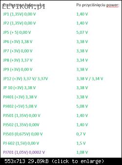
Szybko sprawdziłem obecność napięć na wszystkich zworach JP oraz PJ (w zasadzie jednoznaczne z wyjściami wszystkich przetwornic).
W efekcie wykrycie braku napięć +5VS oraz +3VS. Wizualna inspekcja wykazała. że uszkodzony jest układ U23. Po jego wymianie wszystkie napięcia obecne (zarówno z grupy ALW czyli obecne już po podpięciu ładowarki oraz po przyciśnięciu przycisku power). Wyniki pomiarów jak niżej.
Immagine
JP12 fabrycznie w tej płycie nie jest zwarty dlatego pomiar napięcia z obu stron.

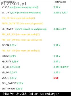
No to następna moja myśl pewnie coś z sekwencją sygnałów uruchomieniowych. Więc zgodnie ze schematem prześledziłem. Wyniki jak niżej:
Immagine

Wyniki w kolumnie odniesienie to pomiary które wykonywałem w czasie naprawy innego egzemplarza już po naprawie (pomyślałem, że mogą przydać się jako odniesienie w przyszłości i się nie pomyliłem).

Sygnały zaznaczone kolorem pomarańczowym to sygnały których nie mogłem zmierzyć bo nie miałem fizycznego podejścia do nich. Ale drogą dedukcji skoro pojawia się sygnał SUSP# to znaczy że wszystkie pomarańczowe sygnały (generowane prze PCH) muszą być poprawnie generowane skoro pojawiają się te, które w sekwencji powinny wystąpić później. Jak widać w naprawianej płycie głównej brak w sekwencji sygnału VGATE dlatego płyta po kliknięciu power zaświeca się na chwilę jednocześnie zamieli jednym wentylatorem i się wyłącza.

No to dałem nura w poszukiwaniu powodu braku sygnału VGATE. Próbowałem znaleźć szczegółowy datasheet TPS51631 (na płycie PU1101) ale na stronie TI jest tylko jakaś ogólna informacja o numerze rysunku i typie obudowy układu plus dostępne sposoby konfekcjonowania (np. taśma). Ostatecznie więc doszedłem do wniosku, że nie ma sensu koncentrować się na tym układzie bo brak na nim sygnału VGATE to zaledwie skutek, wierzchołek góry lodowej a pierwotna przyczyna siedzi niżej.

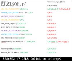
Z braku laku wpadłem na pomysł zbadania sygnałów z GOOD w nazwie. Domyślam się, że ich zadaniem jest raportowanie do PCH, EC i CPU że przetwornice pracują i w ten sposób "meldują się".
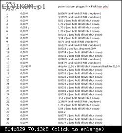
I tu zaczyna się ciekawie, wyniki pomiarów poniżej:
Immagine


Tutaj podobnie wykorzystałem w pierwszej kolumnie jako odniesienie wykorzystałem sygnały które kiedyś pomierzyłem w czasie nauki na jednej z takich samych płyt głównych po naprawie. Prawa kolumna to płyta główna która jest przedmiotem tego wątku. Tam gdzie w punkcie pomiarowym na schemacie był rezystor a w rzeczywistości na płycie głównej go nie było wykonałem pomiary dla obydwu węzłów (node), których numeracja jest zgodna z boardview i ze schematem.

Przyznam szczerze, że tutaj nie mam wypracowanej metodyki na szybką analizę tego typu usterek dlatego zwracam się z prośbą do forumowiczów o porady. Z góry przepraszam, jeśli wątek jest napisany zbyt amatorsko. Jeśli chodzi o sprzęt to dysponuję wszystkim co potrzebne (oscyloskop, termowizja, zasilacz laboratoryjny) z wyjątkiem stacji do reballingu GPU i CPU. I speak English.

Re: Lenovo Y50-70 ZIVY2 LA-B111P rev: 1A Y50-70 brak sygnału VGATE


da Google Adsense [BOT] 27 febbraio 2024, 20:28

#3 Re: Lenovo Y50-70 ZIVY2 LA-B111P rev: 1A Y50-70 brak sygnału VGATE


da Jarek91 29 febbraio 2024, 17:48
Machine ha scritto:You write that you were unable to measure the signals in orange.
I'll give you the example of the PBTN_OUT signal, which is easily measured on pin 106 of the KBC.


Thank you for yours valuable advice.
According to orange signals ON_OFF is present. It's coordinated with power pushbutton. Isn't it?
PBTN_OUT# is ALWAYS present 3,38 V (with charger only)/3,34 V (after pwr bttn pushed)
PM_SLP_S5# jump to 3,35 V for split of second but finally reach 0 V (before motherboard shut down)
PM_SLP_S4# jump to 3,32 V for split of second but finally reach 0 V (before motherboard shut down)
PM_SLP_S3# jump to 3,32 V for split of second but finally reach 0 V (before motherboard shut down)


Dziękuję za Twoją cenną uwagę. Jak widać zakładanie czegoś z góry nigdy nie jest właściwe.
W nawiązaniu do Twojej rady dokonałem pomiarów tych sygnałów. Wyniki poniżej:
PBTN_OUT# jest ZAWSZE obecny 3,38 V (z podłączoną ładowarką)/3,34 V (po wciśnięciu przycisku power)
PM_SLP_S5# na kilka milisekund osiąga 3,35 V ale ostatecznie spada do 0 V (jeszcze zanim wyłączy się płyta główna)
PM_SLP_S4# na kilka milisekund osiąga 3,35 V ale ostatecznie spada do 0 V (jeszcze zanim wyłączy się płyta główna)
PM_SLP_S3# na kilka milisekund osiąga 3,35 V ale ostatecznie spada do 0 V (jeszcze zanim wyłączy się płyta główna)

#4 Re: Lenovo Y50-70 ZIVY2 LA-B111P rev: 1A Y50-70 brak sygnału VGATE


da Machine 2 marzo 2024, 10:28
Having voltage on the PM_SLP_S signals means that the PCH responds to the KBC.
Measure the voltages on all coils (if necessary press the start button several times).
If any coil is at 0V, measure the resistance to ground.

#5 Re: Lenovo Y50-70 ZIVY2 LA-B111P rev: 1A Y50-70 brak sygnału VGATE


da Jarek91 2 marzo 2024, 16:28
Machine ha scritto:Having voltage on the PM_SLP_S signals means that the PCH responds to the KBC.
Measure the voltages on all coils (if necessary press the start button several times).
If any coil is at 0V, measure the resistance to ground.


Thank you for your assistance. Requested measurement results are below:

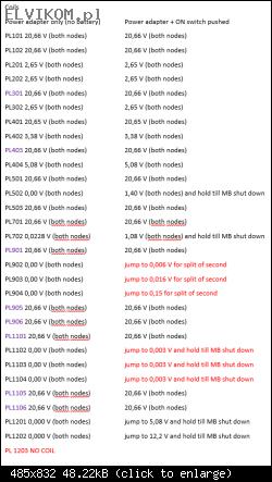
Immagine

According to PL702 measurements. On coil PL702 0,0228 V is availaable only for a first time only when I unplug DC power adapter and plug it to socket (no pressing power button) after pressing this button 1,08V appears and drop to 0,0002 V when MB shut down.

PL902, PL903, PL904 resistance to ground (each) is 13,3 Ω (as far as I know should be here c.a. 6,2 Ω)
PL1102, PL1103, PL1104 resistance to ground (each) is 47,3 Ω (as far as I know should be here c.a. 20,5 Ω)

#7 Re: Lenovo Y50-70 ZIVY2 LA-B111P rev: 1A Y50-70 brak sygnału VGATE


da Jarek91 6 marzo 2024, 11:04
Machine ha scritto:Measure the voltages on all pins of PU1101, PU901.


Thank you again!

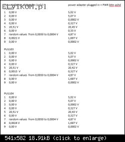
Here are voltage measurement results:
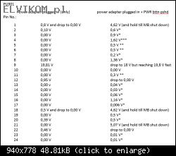
PU1101
Immagine

and PU901
Immagine

* means that the recorded voltage value is the maximum voltage value recorded during several attempts to start the motherboard, which, regardless of the initial value, drops to zero almost immediately;

** means the initial voltage value achieved only during the first start-up attempt after connecting the power supply, which drops to zero almost immediately, each subsequent attempt gave a stable zero from the beginning to the end

*** the first time it reaches a random value not exceeding 1.5 V and drops to 0.0023 V (in the case of connecting the power supply after a long break and trying to start the motherboard), each subsequent attempt from the beginning to the end gives 0.00 V, after turning off the MB return is 0.0023 V

#9 Re: Lenovo Y50-70 ZIVY2 LA-B111P rev: 1A Y50-70 brak sygnału VGATE


da Jarek91 7 marzo 2024, 10:15
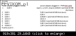
Machine ha scritto:Measure the voltages on all pins of PU1104.


Thank you for your response. Below ae requested voltage measurement results.

Immagine

#11 Re: Lenovo Y50-70 ZIVY2 LA-B111P rev: 1A Y50-70 brak sygnału VGATE


da Jarek91 7 marzo 2024, 15:43
Machine ha scritto:I can't find the PU1101 datasheet to see the correct voltage values. Try replacing it.

As far as I know PU1101, 1102, 1103 are the same IC's. Should I replace all of them or PU1101 only?

#13 Re: Lenovo Y50-70 ZIVY2 LA-B111P rev: 1A Y50-70 brak sygnału VGATE


da Jarek91 10 marzo 2024, 12:20
Machine ha scritto:From the schematic PU1101 (TPS51631ARSMR) is different from PU1102, PU1103. Try replacing PU1101 only.

As always, thank you very much for your time.
Regarding my last answer, I actually wrote nonsense (out of fatigue) and confused the PU1101 IC (TPS51631ARSMR) with three ICs PU1102, PU1103 and PU1104. I'm so sorry.

After replacing the PU1101 (TPS51631ARSMR), we have made a step forward. The motherboard now boots up permanently. It starts one of the first fan and then stops it. In a functional motherboard, after stopping and pausing for a while, two fans should start running.
The GPU stabilizes its temperature at approximately 60 degrees Celsius, similarly to the PCH. The CPU shows no activity in thermal imaging (temperature at the laminate level).

#15 Re: Lenovo Y50-70 ZIVY2 LA-B111P rev: 1A Y50-70 brak sygnału VGATE


da Jarek91 13 marzo 2024, 19:40
Machine ha scritto:Do you have voltage on PL1102, PL1103, PL1104?

voltages on the mentioned IC are attached below. Sorry for the moment of silence, but I had a terrible time at work.

Immagine

It seems to me that on pins 4 and 6 of each IC should be about 1.7 V, while on pin 7 in each IC should be something like 6.7 V. I also have suspicions about the voltage value on pin 8

#17 Re: Lenovo Y50-70 ZIVY2 LA-B111P rev: 1A Y50-70 brak sygnału VGATE


da Jarek91 14 marzo 2024, 12:29
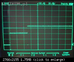
Machine ha scritto:You can measure, with an oscilloscope, the signal on pin 8 of PU1102, PU1103, PU1104.


The oscillograms on pin 8 of each integrated circuit are the same. They resemble stairs. The first level is 0.00V. When the power button is pressed, the voltage increases to 1.078 V and this state lasts for approximately 50.8 ms, and then the voltage increases to approximately 1.703 V and lasts permanently until the motherboard is turned off.

Immagine

I'm sorry that this is a photo of the oscilloscope screen, which sounds amateurish, but I haven't had time to learn the software for the HP54600B that will allow me to export oscillograms to Windows 10, although I have both a serial and parallel expansion module for this oscilloscope.

#19 Re: Lenovo Y50-70 ZIVY2 LA-B111P rev: 1A Y50-70 brak sygnału VGATE


da Jarek91 14 marzo 2024, 17:00
Machine ha scritto:I'm afraid there's a CPU taste.

Can I perform any other measurements to confirm CPU damage?
Which of the ones done so far were particularly important in the context of the CPU? (in case I want to repeat them to be sure?)

I must admit that I wouldn't have been able to do it on my own.
Probably after many days I would also decide to replace PU1101 mainly because there is no data sheet available for it. Then next up would be PU901.

Edit: 21.12.2024 r.
So I made an attempt to replace the processor.
From the motherboard with the damaged PCH I soldered the processor out, put new lead balls from PMTC and soldered in the WDS-620. This was my first attempt (unfortunately unsuccessful). But I'm not giving up. I will desolder the CPU again do a motherboard diagnostic and make another approach. I'll let you know in a while how the progress is.

Re: Lenovo Y50-70 ZIVY2 LA-B111P rev: 1A Y50-70 brak sygnału VGATE


da Google Adsense [BOT] 14 marzo 2024, 17:00
Questo argomento è contrassegnato come D'ARCHIVIO. Rispondi solo se il tuo messaggio contiene la soluzione (Termini e Condizioni p. 12.1).

Chi c’è in linea

Visitano il forum: Nessuno e 7 ospiti

_______________________________
Tutti i diritti riservati. È severamente vietata la copia non autorizzata del contenuto di questo sito Web o di qualsiasi sua parte.
Eventuali marchi, nomi di società, prodotti o servizi pubblicati su questo sito Web appartengono ai legittimi proprietari, sono protetti da copyright e utilizzati solo a scopo informativo.