
Forumsregeln: Die Forumsregeln lesen
- Der Titel des Themas sollte Folgendes enthalten: den Hersteller der Maschine, das vollständige Modell und die kurze Beschreibung des Fehlers.
- Die Themennachricht sollte enthalten: einen PCB-Markierungscode (im Falle von Hardware-Reparaturen), erweiterte Beschreibung des Fehlers, Was wurde überprüft/ersetzt/gemessen + Schlussfolgerungen und, die Frage. Wenn Sie keinen PCB-Markierungscode finden können, du solltest lesen DIESES THEMA. Wenn Sie immer noch keine PCB-Markierungscode finden können, laden Sie bitte ein sauberen Fotos von beiden Seiten des Motherboards - ist es erforderlich, alle Filme und Module zu entfernen, die möglicherweise diese Markierungen abdecken könnte.
- Bevor Sie ein neues Thema veröffentlichen, sollten Sie alle Themen im Unterforum AUSBILDUNGEN lesen und machen Sie eine vorläufige Diagnose basierend auf dem Inhalt dieser Ausbildungen.
- Das Hochladen vollständiger Anweisungen/Schaltpläne oder BIOS-Dateien / Firmware (oder das Verlinken auf andere Websites mit solchen Dateien) ist STRENG VERBOTEN. Sie können nur den kleinen Teil der Anweisung/Schaltplans oder den Link zur BIOS-Datei in UNVERIFIZIERTE BIOS-DATEIEN platzieren, der die Diagnose und Reparatur für den Themenautor vereinfacht. Sie können nicht mehr als eine vollständige Seite mit Anweisungen/Schaltplänen pro einzelnem Thema platzieren. Die Datei darf keine sichtbaren Wasserzeichen, "vertraulichen" Markierungen, E-Mail-Adressen usw. enthalten.
- Pro Thema darf nur eine fehlerhafte Maschine beschrieben werden. Für jede nächste Maschine sollten Sie ein neues Thema öffnen.
- Das Anfordern von Schaltplänen, Boardview, MB-Fotos, BIOS-Dateien oder Servicehandbüchern ist STRENG VERBOTEN. Wenn Sie irgendwelche von denen fragen wollen, sollten Sie ein neues Thema in DOKUMENTATION UND BIOS/EFI ANFRAGE Sub-Forum öffnen.

Re: Re: Acer Nitro 5 AN-515 LA-H501P Martwy
von Google Adsense [BOT] • 6 März 2025, 13:54


Sorry, but your pictures are not clear at all and are more or less useless for further diagnostics.
We are interested in a quality sharp picture of the marked area with clearly visible copper traces and vias on the board.
By the way, it's not necessary to post a picture of 1/4 of the entire board, we are only interested in the 5x5cm area, as marked with a yellow rectangle in post #22.
We are interested in a quality sharp picture of the marked area with clearly visible copper traces and vias on the board.
By the way, it's not necessary to post a picture of 1/4 of the entire board, we are only interested in the 5x5cm area, as marked with a yellow rectangle in post #22.


These pictures are better.
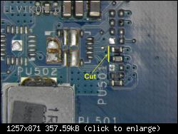
It seems there is a short circuit between the layers somewhere inside the PCB board.
Cut the copper trace on the board as shown in the picture below and remeasure the voltages to ground on both pins of resistor PR504. The board is multi-layer, so be careful to not cut too deep (cut the top copper layer only).

psikus123 hat geschrieben:Po podłączeniu zasilania na pin 12 PU502 pojawiło się 3,3VI didn't noticed that the resistor PR505 is also present on the board (it's actually a copper trace on the PCB).
So that means something is wrong with the signal line "MAINPWON". It pulls the line "5V_3V_EN" to the low state).
psikus123 hat geschrieben:Czy mogę montować PU502 i próbować uruchamianie płyty?Yes, you can, but the board will not work as the signal "MAINPWON" is interrupted now.
- Restore the cut copper trace - you can solder a 0Ω resistor to the place of PR505.
- Remove the transistor Q1 from the board and check if 3V is still present on pin 12 of chip PU502.
KBC programowałem 4 wsadami, które zdobyłem z forów także elvikom.
Wymieniłem KBC 2 razy, pierwszy z partii, które kiedyś kupiłem z Chin oraz znalazłem na płycie co mam na części, wszystkie programują się i weryfikują pozytywnie.
Myślę, że problem KBC jest wykluczony , na każdym wsadzie i KBC na pin 12 PU512 jest 0,07V.
Sprawdziłem wszystkie elementy na linii MAINPWON profilaktycznie wymieniłem DB1.
Gdzie szukać dalej?
Re: Acer Nitro 5 AN-515 LA-H501P Martwy
von Google Adsense [BOT] • 10 März 2025, 10:10
Wer ist online?
Mitglieder in diesem Forum: 0 Mitglieder und 10 Gäste
_______________________________Alle Rechte vorbehalten. Das unerlaubte Kopieren des Inhalts dieser Website oder eines Teils davon ist strengstens untersagt.
Alle auf dieser Website veröffentlichten Marken, Markennamen, Produkte oder Dienstleistungen gehören ihren gesetzlichen Eigentümern, sind urheberrechtlich geschützt und werden nur zu Informationszwecken verwendet.